Overview of Maxim's Charger Offerings
Ron
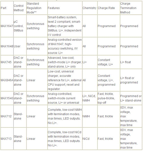
Maxim manufactures a broad selection of stand-alone and controller-type battery-charger ICs. The variety enables a system designer to make tradeoffs in performance, features, and cost. Table 1 lists these ICs by the battery chemistry supported, in their order of introduction, with the most recent models at the top.
Table 1. Overview of Maxim's Battery-Charger ICs

* The use of a DAC and µC is also possible with the DAC-input types.
** All linear types can be used in a hysteretic switching mode for higher efficiency.
The choice between linear and switch-mode regulation constitutes a major design decision. Linear mode is less costly, but it dissipates power and gets hot. Heat may not be a problem in large desktop chargers, but it can be unacceptable in smaller systems such as a notebook PC. Synchronous switching regulators offer the highest efficiency (in the mid-90% range), which makes them suitable for the smallest systems, including cell phones. Some of the nonsynchronous switch-mode circuits listed also offer reasonable efficiency. In addition, most of the linear parts can be used in a moderately efficient hysteretic switching mode. (For details, consult the appropriate data sheet.)
The charger's level of autonomy poses another design decision. Stand-alone chargers, for example, are completely self-contained. The MAX712/MAX713 and have LED-control outputs for the user's end equipment as well.
Other devices can stand alone or can operate with a digital-to-analog converter (DAC) and µP. They include the MAX1640/MAX1641, MAX846A, and MAX745. The MAX1640, a voltage-limited current source intended primarily for charging nickel-chemistry batteries, includes a charge timer and pulse-trickle circuitry. It has stand-alone features and operates with a high-efficiency synchronous switching regulator or (for lower cost applications) a standard switcher.
The MAX846A and MAX745 are both capable of stand-alone operation in charging Li+ batteries, and they include the high-accuracy reference and independent voltage and current control necessary for universal controllers. The MAX846A is a linear type, and the MAX745 is a synchronous-switching type. Though either can stand alone, they usually operate with a µC that provides limited control of the charging process. LED illumination and fast-charge termination are usually initiated by the software. The MAX846A includes a linear regulator and a CPU-reset output for the µC.
The least autonomous and most flexible devices are the MAX1647 and MAX1648. They are similar, except the MAX1647 has built-in DACs and an SMBus serial port, and the MAX1648 has analog inputs for voltage and current control. The MAX1647 is a complete, serially controlled dc power supply with independent voltage and current registers. Capable of SMBus communications with a smart battery, it provides Level 2 compliance with the Intel/Duracell smart-battery specification.
µC Design TipsThese charger ICs typically operate with a low-cost 8-bit controller such as the 8051, PIC, 68HC11, or 68HC05. The firmware can be written in assembly language or in C, either of which feature ready availability, low cost, and free tools. Third parties and manufacturers of these devices have assembled an impressive array of compilers, assemblers, emulators, and code libraries. Much of this source code is available on the World Wide Web, especially the toolbox routines for assembly language. The Tips for charger program structure section provides further information on these resources.
All common 8-bit µCs are suitable, but the selection of a specific µC is beyond the scope of this article. Peripherals such as analog-to-digital converters (ADCs), DACs, and the SMBus serial interface are available in these µCs, and simpler µC versions that require external ADCs or DACs are also useful. Often, simpler µC versions that require external ADCs or DACs are more flexible and ultimately more useful.
The ROM and RAM requirements for charger applications are modest. In general, you can implement a single-chemistry charger in less than 0.5kbytes of code and 32 bytes of RAM (simple requirements for even a low-end PIC). With some ingenuity, you can implement a multi-chemistry charger with about 50% more code
The simplest way to develop µC code is to start with a skeleton or a piece of similar code, and modify it to suit your needs. This approach gets a prototype working quickly by overcoming a lot of the blank-page, compiler/assembler- syntax problems. Unfortunately, only a limited amount of battery-charger firmware exists on the Web and in standard application notes. However, two design examples in the Hardware and Software Examples section provide a starting point. See the Resources and references section for more information on some of the more difficult toolbox routines, such as SMBus communications and math routines, and for examples of program designs that illustrate approaches to these designs.
